
Circuits
You ask
Will a blue LED on 5 V with a 47 ohm resistor fry?
Wobbl runs
$ wobbl simulate "a blue LED on 5 V with a 47 ohm resistor" "Will a blue LED on 5 V with a 47 ohm resistor fry?" \ --set supply=5V --set resistor=47 --set led=blue
Series resistor 47 ohm of 47 ohm
peak share of its limit
0.256
FAILS
LED current 36.9 mA, supply current 36.9 mA
Checks, numbers and charts
FAILSThe LED fries: 36.9 mA through it, above its 30 mA rating (1.2x).
- LED current
- 36.9 mA
- Rating
- 30 mA
- Resistor power
- 63.9 mW
- Confidence
- high
- passhand calculation
- passpower balance
- infooperating limits
FAILS. The LED fries: 36.9 mA through it, above its 30 mA rating (1.2x). Confidence: high. passed hand calculation, power balanceLED current: 36.9 mArating: 30 mAresistor power: 63.9 mWLED power: 120 mW Checks: [pass] hand calculation: diode equation solved by hand gives 36.9 mA, ngspice 36.9 mA (5.4e-05% apart); the quick estimate (Vs - Vf)/R is 38.3 mA [pass] power balance: supply gives 184 mW = resistor 63.9 mW + LED 120 mW (5.4e-08% apart) [info] operating limits: LED 36.9 mA of 30 mA; resistor 63.9 mW of 250 mW Assumptions: - blue LED modeled with the diode equation: 3.2 V at 20 mA, ideality 2.7, series resistance 1.5 ohm. - Resistor 47 ohm exact, rated 0.25 W. - Room temperature, steady DC. Suggested fixes: - Use a 91 ohm resistor: Gives about 19.8 mA; it dissipates 35.6 mW, so a 0.25 W part is enough. Images: setup: images/setup.svg, schematic: images/schematic.svgReport: report.htmlYou ask
What is the ripple on this 12 V to 5 V buck at 2 A?
Wobbl runs
$ wobbl simulate "12 V to 5 V buck converter at 2 A" "What is the ripple on this 12 V to 5 V buck at 2 A?" \ --set vin=12 --set vout=5 --set current=2 --set frequency=500k \ --set inductor=10u --set capacitor=22u --set max_ripple=0.05
Load current 2 A of 2 A
peak share of its limit
0.164
OK
Output ripple 8.17 mV, output 5.07 V
Checks, numbers and charts
OKOutput ripple 8.56 mV peak to peak on 5.07 V (within the 50 mV limit); inductor ripple 0.604 A, peak 2.33 A.
- Ripple
- 8.56 mV
- Output
- 5.07 V
- Inductor ripple
- 0.604 A
- Confidence
- high
- passhand calculation
- passsteady state
- passtime step convergence
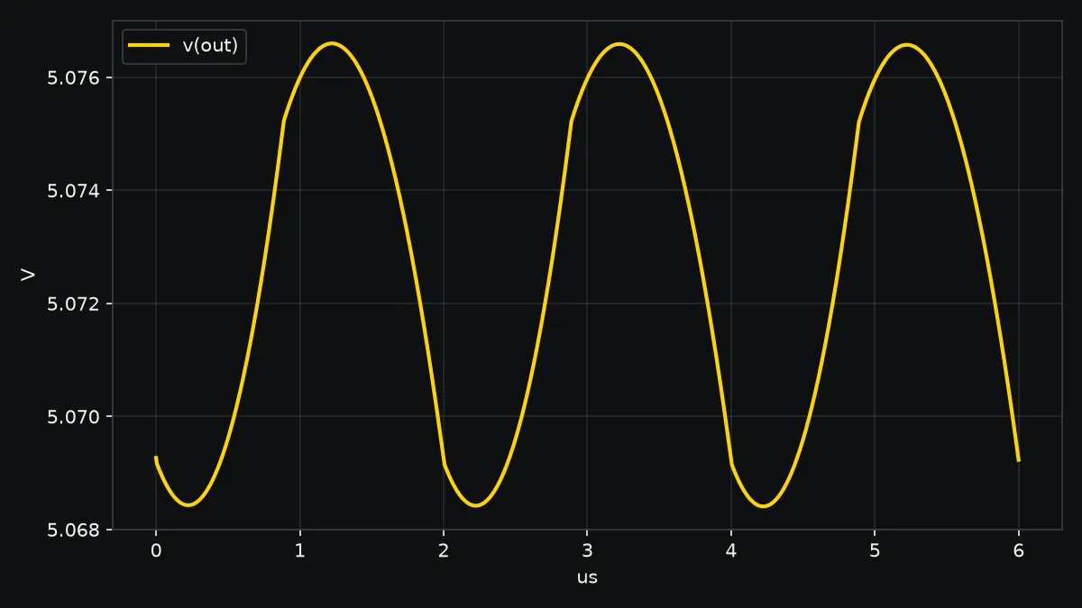
OK. Output ripple 8.56 mV peak to peak on 5.07 V (within the 50 mV limit); inductor ripple 0.604 A, peak 2.33 A. Confidence: high. passed hand calculation, steady state, time step convergenceripple: 8.56 mVoutput: 5.07 Vinductor ripple: 0.604 Aduty: 43.7% Checks: [pass] hand calculation: ideal waveform math (triangular inductor ripple dI = 0.583 A through C and ESR) gives 7.95 mV; ngspice 8.56 mV and 0.604 A (8% apart; the math ignores switch and diode drops) [pass] steady state: average output moved 0.0069% between the last two 20 cycle windows [pass] time step convergence: output ripple 0.00856 with the normal step, 0.00856 with half the step (0.0022% apart) Assumptions: - Open loop at the steady state duty cycle 43.7%; real controllers add their own ripple and transients. - Switch on resistance 0.05 ohm, Schottky catch diode. - Capacitor ESR 10 mohm, no ESL. Images: waveform: images/waveform.png, setup: images/setup.svg, schematic: images/schematic.svgReport: report.htmlYou ask
How hot does this MOSFET get switching 15 A at 20 kHz in a 50 C box?
Wobbl runs
$ wobbl simulate "a MOSFET with 8 mOhm Rds on switching 15 A at 20 kHz" "How hot does this MOSFET get switching 15 A at 20 kHz in a 50 C box?" \ --set current=15 --set rds_on=8m --set frequency=20k --set theta_ja=40 \ --set ambient=50
Load current 15 A of 15 A
peak share of its limit
0.604
OK
Junction 110 C, loss 1.51 W
Passes the 1 limit at 18.1 A
Checks, numbers and charts
OKJunction reaches about 110 C (1.51 W: 1.37 W conduction, 0.144 W switching) with 40 C/W to 50 C air; limit 150 C.
- Junction
- 110 C
- Limit
- 150 C
- Loss
- 1.51 W
- Confidence
- high
- passhand calculation
- passthermal loop
OK. Junction reaches about 110 C (1.51 W: 1.37 W conduction, 0.144 W switching) with 40 C/W to 50 C air; limit 150 C. Confidence: high. passed hand calculation, thermal loopjunction: 110 Climit: 150 Closs: 1.51 Wtheta JA: 40 C/W Checks: [pass] hand calculation: conduction loss I_rms^2 R = 0.903 W; ngspice average of V x I = 0.903 W (0.00079% apart) [pass] thermal loop: junction settles at 110 C after the on resistance warms up (12.1 mohm hot) Assumptions: - On resistance 8 mohm at 25 C rising 0.6% per C. - Switching loss from 40 ns edges: 0.5 V I (tr + tf) f. - Junction to air 40 C/W (datasheet, no heatsink unless included). Images: setup: images/setup.svg, schematic: images/schematic.svgReport: report.htmlYou ask
Will anything on this board overheat with a 2 A LED strip on J2?
Wobbl runs
$ wobbl simulate kicad-board.kicad_sch "Will anything on this board overheat with a 2 A LED strip on J2?" \ --set J2.load=2A
J2 load current 2 A of 2 A
peak share of its limit
0.528
OK
Hardest part 52.8 % of rating, supply current 2,006 mA
Passes the 1 limit at 5.98 A
Checks, numbers and charts
OKWorks and nothing is stressed: the hardest working part is C1 (capacitor) at 53% of its voltage rating.
- Hardest part
- C1 at 53%
- Supply power
- 24.1 W
- Hottest part
- Q1 at 32.7 C
- Confidence
- high
- passKCL
- passpower balance
- passtime step convergence
- passhand calculation
- passhand calculation
- passhand calculation
- passhand calculation
- passmodel provenance
- infosupply range
OK. Works and nothing is stressed: the hardest working part is C1 (capacitor) at 53% of its voltage rating. Confidence: high. passed KCL, power balance, time step convergence, hand calculation, model provenancehardest part: C1 at 53%supply power: 24.1 Whottest part: Q1 at 32.7 Canalysis: transient Checks: [pass] KCL: currents into every node sum to zero within 2.40e-09 A (largest at STRIP-, against 18.7 A flowing) [pass] power balance: over the run the supplies gave 0.0585 J, the parts dissipated 0.0511 J and the capacitors and inductors stored 0.0072 J (1/2 C V^2 and 1/2 L I^2), 0.33% apart [pass] time step convergence: every part's power and current agree to 0.26% with half the time step; the most moved is C2 current: 6.71e-07 and 5.88e-06 [pass] hand calculation: divider R2/R3: 4.98 V x 10000 / (100 + 10000) = 4.93 V by hand, ngspice 4.93 V (4e-06% apart) [pass] hand calculation: R1 into D1: the diode equation solved by hand gives 5.43 mA, ngspice 5.43 mA (4.4e-05% apart) [pass] hand calculation: U1 dissipates (Vin - Vout) Iout + its own current: 0.136 W by hand, 0.136 W from its pins (2.7e-11% apart) [pass] hand calculation: Q1 conduction loss I_rms^2 R_ds(on) = 1.99^2 x 30 mohm = 0.119 W by hand, ngspice 0.119 W (0.25% apart) [pass] model provenance: models: 11 from the parts library [info] supply range: solved at both ends of the supply (J1 10.8 to 13.2 V (10% either way, a guess)); the hardest parts there: C1 at 53%, C3 at 34%, Q1 at 34% Assumptions: - Wobbl guessed: air temperature around the board not given, so Wobbl assumed 25 C. - Wobbl guessed: J2 (LED strip) drives 2A, as set. - U1: L7805 datasheet: 5 V, 2 V dropout at 1.5 A, 2.2 A limit, 35 V most in, TO-220. - C1: 25 V rating as marked, aluminum. - U2: ATTINY85 datasheet: 2.7 to 5.5 V (6 V absolute), about 5 mA running, pins drive through about 40 ohm and take 40 mA most. - D1: green 0805 indicator LED: 3.1 V at 20 mA, 30 mA most. - Q1: VDMOS fitted to the IRLZ44N datasheet: 22 mohm at 10 V, 25 mohm at 5 V, 35 mohm at 4 V, threshold 1.5 V, 55 V 47 A TO-220. - J2 load: what J2 drives, 2A. - Ambient 25 C; temperatures are ambient plus average power times each part's thermal resistance. - Transient: run for 0.0036 s, six of the longest time constant (0.0006 s). - Transient: outputs switch on at power up and off at 60% of the run, so both states and the switch off are seen. Images: setup: images/setup.svg, schematic: images/schematic.svgReport: report.htmlYou ask
Is this buffer stable driving the cable?
Wobbl runs
$ wobbl simulate opamp-cable.cir "Is this buffer stable driving the cable?"
CCABLE capacitance 1 uF of 1 uF
peak share of its limit
1.96
FAILS
U1 phase margin 1.95 deg, XU1 load 196 % of limit
Passes the 1 limit at 0.00214 uF
Checks, numbers and charts
FAILSU1 (LM358) does not work as wired: 2 degrees of phase margin at 47133 Hz: it oscillates or rings hard.
- Hardest part
- CCABLE at 16%
- Supply power
- 0.00313 W
- Hottest part
- U1 at 25.2 C
- Confidence
- high
- passKCL
- passpower balance
- passtolerance convergence
- passmodel provenance
- infoloop stability
FAILS. U1 (LM358) does not work as wired: 2 degrees of phase margin at 47133 Hz: it oscillates or rings hard. Confidence: high. passed KCL, power balance, tolerance convergence, model provenancehardest part: CCABLE at 16%supply power: 0.00313 Whottest part: U1 at 25.2 Canalysis: operating point Checks: [pass] KCL: currents into every node sum to zero within 7.50e-10 A (largest at ref, against 6.25e-04 A flowing) [pass] power balance: supplies give 0.00313 W and the parts dissipate 0.00313 W (0.00016% apart) [pass] tolerance convergence: every part's power and current agree to 0% with solver tolerances 100 times tighter [pass] model provenance: models: 7 from the parts library [info] loop stability: U1: loop gain 99879 at low frequency crosses 1 at 47133 Hz with 2 degrees of phase margin and 5 dB of gain margin; it will ring hard or oscillate Assumptions: - Wobbl guessed: air temperature around the board not given, so Wobbl assumed 25 C. - V1: USB port: 5 V (4.75 to 5.25 V), 0.15 ohm inside, 0.5 A most. - U1: LM358 datasheet: 0.7 MHz, 0.3 V/us, swing to 1.5 V of V+ and 0.02 V of V-, 40 mA short circuit, 3 to 32 V supply. - Ambient 25 C; temperatures are ambient plus average power times each part's thermal resistance. Suggested fixes: - Isolate U1 from its capacitive load with 100 ohm: Put 100 ohm between U1's output and CCABLE, with the feedback taken before it, so the load's capacitance is outside the loop. Solved again, U1 now has phase margin 72.3 deg, 72 degrees of phase margin at 444507 Hz: stable. Images: setup: images/setup.svg, schematic: images/schematic.svgReport: report.htmlAbout this example
Will this LED fry, what is the ripple, how hot does the MOSFET get, does anything on this board overheat, and is this buffer stable?
The first three are template questions, each answered with ngspice and checked against the textbook answer computed independently. The last two are a circuit of the user’s own: a KiCad schematic of a small board and a SPICE netlist. Wobbl reads them, gives every part its library model and ratings, picks the analyses, judges every part, checks itself and solves its fixes again before offering them.
| Question | Answer | Checks |
|---|---|---|
| Will a blue LED on 5 V with a 47 ohm resistor fry? | Yes, 36.9 mA goes through a 30 mA LED, and Wobbl suggests 91 ohm for about 20 mA | the diode equation by hand gives 36.9 mA and ngspice 36.9 mA, and the supply’s power equals the resistor’s plus the LED’s |
| What is the ripple on a 12 V to 5 V buck at 2 A, 500 kHz, 10 uH, 22 uF? | 8.56 mV peak to peak with 0.60 A of inductor ripple, within a 50 mV limit | the ideal triangular ripple math gives 7.95 mV, 8% apart because of the switch and diode drops, the output reached steady state, and the ripple is the same at half the time step |
| How hot does a MOSFET get switching 15 A at 20 kHz in a 50 C box with 40 C/W to air? | About 110 C at the junction from 1.51 W, under the 150 C limit with margin | the conduction loss I_rms^2 R matches the simulated V x I to 0.001%, and the junction temperature is iterated with the on resistance rising 0.6% per C |
| Will anything on this board overheat with a 2 A LED strip on J2? (a 12 V jack, an L7805, an ATtiny85 lighting an LED and switching an IRLZ44N) | No. The hardest working part is C1 at 53% of its 25 V rating, the IRLZ44N runs at 33 C and the 7805 at 32 C | KCL, the power account, half the time step, four hand calculations (the gate divider, the LED’s diode equation, the regulator’s dissipation and the MOSFET’s I_rms^2 R loss) and both ends of the supply range |
| Is this LM358 buffer stable driving a cable of about 1 uF? | No. Its loop gain crosses 1 at 47 kHz with 2 degrees of phase margin, so it oscillates. Wobbl adds 100 ohm between the output and the cable with the feedback taken before it, sweeps the loop again and gets 72 degrees | the loop gain is Bode’s return ratio of the op amp’s gain stage, cut for AC only, and the fix is solved again before it is offered |
Each folder holds report.html, summary.txt, outcome.json, the netlist Wobbl solved,
playback.json with every part’s voltage, current and power over the run for the site to animate,
and the bench and schematic drawings in images/.
Each run also has a 3D bench you can work with (wobbl view led). A slider sets the one input its
question points at and the circuit is solved again at every step. The LED run moves the series
resistor from 15 to 470 ohm, the buck and MOSFET runs move the load current, the board moves the
current of the strip on J2 up to 6 A, and the buffer moves the cable’s capacitance from 1 nF to
10 uF. Each part is shaded by its share of its limit, and the LED glows with its current.
Run it yourself
$ git clone https://github.com/sohan-bhat/wobbl$ cd wobbl/examples/circuits && ./run.shThe part, the script and every output are in examples/circuits on GitHub.